EN ISO 13849-1: Performance Level (PL)

EN ISO 13849-1: Performance Level (PL)

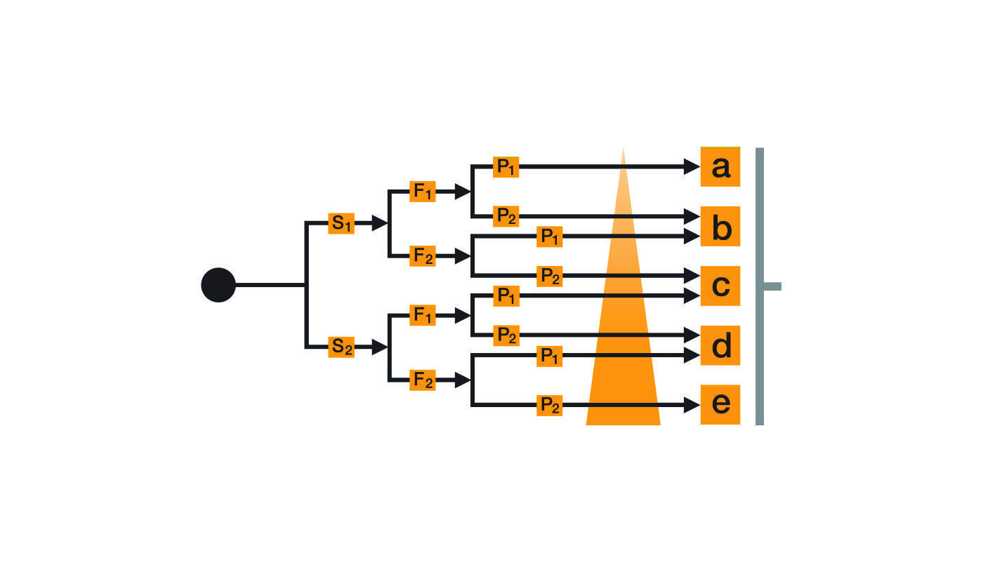
The greater the risk, the higher the requirements of the control systems. The hazardous situation is classified into five levels, known as Performance Levels (PL), from PL "a" (low) to PL "e" (high). The required PL is determined and assigned as part of the risk assessment in accordance EN ISO 13849-1.

EN ISO 13849-1/-2: Safety of machinery – Safety-related parts of control systems

As the successor to EN 954-1, EN ISO 13849-1 is the main safety standard for the design of safety-related control systems for machinery.

Performance Level

In contrast to the previous standard EN 954-1, which took a deterministic (reproducible) approach, EN ISO 13849-1 is based on a probabilistic approach to assessing safety-related control systems.

As well as dealing with electrical, electronic and programmable electronic systems, the standard also considers other control technologies, such as fluid power for example

The proven categories from EN 954-1 have been retained, but safety-related properties are also assessed quantitatively through statistical calculation methods. A Performance Level is determined, based on the categories. This is described by the following parameters:

  • Category (structural requirement)
  • Mean time to dangerous failure (MTTFd)
  • Diagnostic coverage (DC) and
  • Common cause failure (CCF)


EN ISO 13849-2 Safety of machinery - Safety-related parts of control systems

By validation we mean an evaluated examination, including analysis and testing of the safety functions and categories of safety-related parts of control systems.


Applicability of EN 954-1

In principle EN 954-1 lost its presumption of conformity with the Machinery Directive 2006/42/EC on 31.12.2011, so actually it may no longer be applied in a conformity assessment procedure for 2006/42/EC.
 

Exception: In individual product standards for specific machine types (e.g. machine tools), application is still permitted under two conditions:


1) EN 954-1 must be noted in the normative references with the issue date

  • EN 954-1:1996
    Example: EN 12417:2001 + A2:2009 Machine tools – Safety – Machining centres

2) EN 954-1 and EN ISO 13849-1 are both listed in parallel in the normative references with the issue date

  • EN 954-1:1996 and EN ISO 13849-1:2006
    Example: EN ISO 23125:2015 – Machine tools – Safety – Turning machines

Reach your goal in six steps

The introduction of EN ISO 13849-1 has also resulted in new procedural requirements for machine design. The design of safety-related parts of control systems is an iterative process, which is completed in several steps.

Step 1 - Define the requirements of the safety functions

This is the most important step. First of all, the required properties must be defined for the safety functions. For safety gate guarding on a machine, for example, hazardous movements must be shut down when the safety gate is opened. It must not be possible for the machine to restart while the safety gate is open.

Step 2 - Determine the required Performance Level (PL)

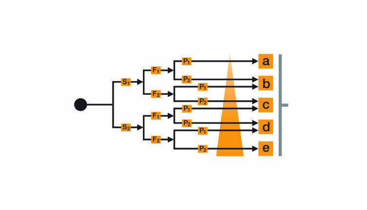
The greater the risk, the higher the requirements of the control system. The contribution of reliability and structure can vary depending on the technology used. The level of each hazardous situation is classified in five stages from "a" to "e". With "a" the control function's contribution to risk reduction is low, with PL "e" it's high. The risk graph can be used to determine the required Performance Level (PL r ) for the described safety function.

Severity of injury (S)
S1 = Slight (normally reversible) injury
S2 = Serious (normally irreversible) injury, including death

Frequency and/or exposure to a hazard (F)
F1 = Seldom to less often and/or exposure time is short
F2 = Frequent to continuous and/or exposure time is long

Possibility of avoiding hazard or limiting harm (P)
P1 = Possible under specific conditions
P2 = Scarcely possible

Step 3 – Design and technical implementation of the safety functions

The "safety gate interlock" safety function described in Step 1 is realised through control measures. The safety gate interlock is implemented using a coded proximity switch such as the PSENcode. This provides the option to connect several safety gates in series without reducing the effectiveness of the monitoring functions. What's more, coding also offers comprehensive manipulation protection. The sensors are evaluated using a multifunctional safety system such as the PNOZmulti. The drive is shut down via two contactors with positive-guided contacts.

Step 4 – Determine and evaluate the performance level

To determine the achieved Performance Level, the safety function is separated into sensor, logic and actuator. Each of these subsystems contributes to the safety function. All the necessary performance data is available for Pilz components. Pilz provides a user-friendly calculation tool (PAScal) for this purpose.

Step 5 – Verification

This step determines the extent to which the achieved Performance Level matches the required Performance Level. The achieved PL must be greater than or equal to the PL r required from the risk assessment. This means a "green light" for the machine design.

Step 6 – Validation

Alongside the purely qualitative requirements for the design of safety systems, it is also important to avoid systematic failures. This happens during validation.

Do you require further information? Please read chapter 3.7! The English Safety Compendium offers knowledge around machine safety.

Safety Compendium
Contact

Pilz Automation Safety L.P.
7150 Commerce Boulevard
Canton, MI 48187
USA

Telephone: +1 734 354-0272
E-Mail: info@pilzusa.com

Technical Support

Telephone: +1 877 745-9872
E-Mail: techsupport-us@pilz.com

Was this article helpful?